22.8.2013 1:46, pesco
tags: code hardware arduino cpld jtag
A good while ago I won one of the free PCBs
regularly given away
by DIY hardware shop
Dangerous Prototypes.
My board of choice was a
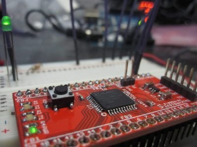
CPLD breakout board,
for the Xilinx XC9572XL.
CPLDs
are the smaller brother of FPGAs:
programmable logic
chips that can be made to act
as any integrated circuit
within the device's limits.
The XC9572XL is programmed via a
standard
JTAG
interface.
I did not have anything that speaks JTAG
so went looking if my Arduino
can be turned into an appropriate programmer.
The
solution that I found,
however, did not work;
so I built my own.
Normally
,
to program a CPLD, or FPGA,
one buys an expensive interface cable
and uses it with the software development suite
supplied by the particular chip's vendor.
Of course there are plenty of DIY alternatives;
in fact, Dangerous Prototypes
sell one
or two.
One of my goals with this project was, however,
to spend next to no money on it.
I got the circuit board for free,
the parts cost around 3EUR,
and I had already done a similar job
with my
Arduino Atmel programmer.
So after soldering the board
I flashed the abovementioned
JTAG code onto the Arduino.
This was my second time SMD-soldering
so I was not expecting the board to work on first try.
But even after checking every connection with a multimeter,
JTAGWhisperer would
do apparently nothing
after receiving the first chunk of data.
I eventually gave up searching for the cause.
Instead I decided to write a very simple
Arduino program that allows
direct interaction
with the JTAG interface from
a serial terminal.
It is called
jtagbang because
it is essentially bit-banging on the
JTAG pins.
By pure coincidence,
it also requires frequent use
of the exclamation mark (
bang
)
when talking to it.
I didn't know anything about JTAG until three days ago.
Now I know that it is awesome.
The point of JTAG is to connect to
any number of chips in some circuit design,
taking up next to no space on the board,
requiring only very simple support from the chip,
and allowing the user to inspect and manipulate
virtually every pin and connection
at any time
without touching anything.
I call it
fucking magic.
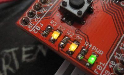
These LEDs are lit because I told the chip
I needed those outputs on for testing purposes.
Unfortunately I cannot explain the magic in the space of this post,
however, here is a link to the
IEEE specification.
While IEEE doesn't want you to read their standards,
someone has helpfully put
the 2001 version on slideshare…
Reading that spec is still not much fun,
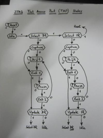
but I made a drawing of the
important part.
So, long story short:
Upload the attached sketch to an Arduino,
take a peek at the top of the file maybe,
and connect to it with a terminal emulator (read
minicom)
or the Arduino IDE's serial monitor (set to line-ending
Newline
).
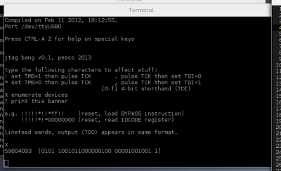
Enter a capital
X and it will interrogate the
JTAG interface
to find all the connected devices (chips).
It lists their built-in identification codes which take the form
of 32 bits in four groups:
59604093 [0101 1001011000000100 00001001001 1]
The groups are, from most to least significant bit:
4-bit product version (
5),
16-bit product code (
9604 is the
XC9572XL),
11-bit manufacturer code (
00001001001 is Xilinx),
and one bit that is always 1 for thaumaturgic reasons.
I should find a PC mainboard to try this with.
Next, I need to get the CPLD programmed.
Xilinx uses (X)SVF files for this,
a file format that describes what to do
on a JTAG interface in a more high-level fashion
than my bit-banging.
I need a
player
for this format that translates
standard SVF commands into
bang language
and vice-versa.
The good thing is that I can now do this
in a high-level programming language of my choice
entirely on the host
instead of cramming it into the Arduino.
The adventure
after that
will be
learning VHDL
and designing an actual integrated circuit.
Attachment:
jtagbang.ino (v0.1)
I am releasing the code under the terms of the
quite permissive
ISC license.


